Raphnet Intellivision Controller To USB Adapter
Product Description:
This adapter makes it possible to use an original Intellivision 1
controller on a computer with an USB port.
Features:
- All 16 directions (+ Idle position) of the disc are functional
- All "Telephone" style buttons are usable
- All 4 side buttons are usable (Top left and Top right are equivalents though)
- No custom drivers required. Device is standard USB Hid (Human Input Device)
Note that the rotating disc and the 12 'telephone' buttons cannot be used at the same time. This is a limitation of the controller, not the adapter.
Project overview
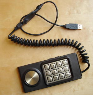 Someone requested that I convert an Intellivision 1 controller to USB. The result
can be seen on the picture on the left. As usual, everything is open-source so you'll
find schematics and source code on this page.
Someone requested that I convert an Intellivision 1 controller to USB. The result
can be seen on the picture on the left. As usual, everything is open-source so you'll
find schematics and source code on this page.A fun part of this project is the fact that I've had no choice but to figure out how the controller worked by myself. I did some research, but could not find any pertinent information about how it worked. But fear not! I have taken the time to create an how it works section to detail my findings.
The key features of the result are:
- All 16 directions (+ Idle position) of the disc are functional
- All "Telephone" style buttons are usable
- All 4 side buttons are usable (Top left and Top right are equivalents though)
- No custom drivers required. Device is standard USB Hid (Human Input Device)
Schematic
A table matching pin numbers to wire colors is given in the how it works section.
Important:
Keep in mind that the pin numbers are for Intellivision 1 controllers only! At the moment, I have no idea what the pinout for other similar controllers would be.
If you wish to try a different controller, I suggest that you use the information in the how it works section and compare with your controller. Be sure to contact me with your results!
Component list:
| Ref | Description |
|---|---|
| U2 | Atmega8 microcontroller. ATMEGA8-16PC, ATMEGA8-16PI, ATMEGA8-16PJ or ATMEGA8-16PU. Dont use an ATMEGA8L-*, the 12Mhz clock would be too high. |
| R1 | 1.5k resistor. Ordinary carbon film 1/4 watt resistors will do. |
| R2, R3 | 68 ohm resistors. Ordinary carbon film 1/4 watt resistors will do. |
| D2, D3 | 3.6 volts zener diodes. |
| Y1 | 12 Mhz crystal. |
| C2, C3 | 18 pf capacitors. If the crystal datasheet recommends another value, use it instead. |
| C1 | 1uf capacitor. Install it near the ATmega8 power pins. |
| J2 | 6 pin header, 2.54mm spacing. Needed for programming the ATmega8. |
For the USB connection, just strip the USB cable and solder the wires directly to the board. USB uses standard wire colors:
| Color | Description | |
|---|---|---|
| Red | +5 volts | |
| Black | Ground | |
| Green | D+ | |
| White | D- |
Programming
intellivusb-1.0.hex
Many microcontrollers have what is called 'Fuse bytes'. In the case of the ATmega8, there are two bytes: The high byte, and the low byte. Those bytes are used to configure some aspects of the microcontroller. What type of clock to use? Crystal? Resonator? Internal RC clock? Allow programming via ISP? It's very important to set the fuses to the right values. Using the wrong values can render your MCU unusable.
For this project, here are the appropriate fuse values:
high byte = 0xc9, low byte = 0x9f
For details about how to program an AVR, visit my AVR programming page.

Source code
intellivusb-1.0.tar.gz
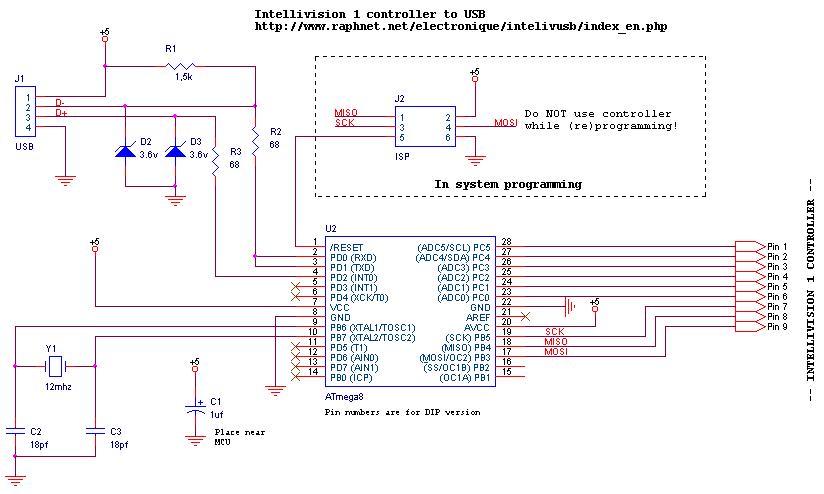
PCB for surface-mount
Multiuse PCB2:
|
Intellivision 1 Wiring: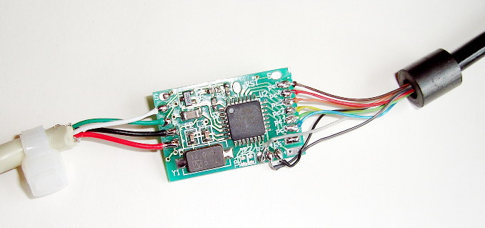
|
How it works
I tried to find information about the controller on the net before beginning
this project but I could not find anything useful. So I had no other choice than
to figure out how the controller worked by myself, which was quite fun. Here's how
it works (at least to my understanding).
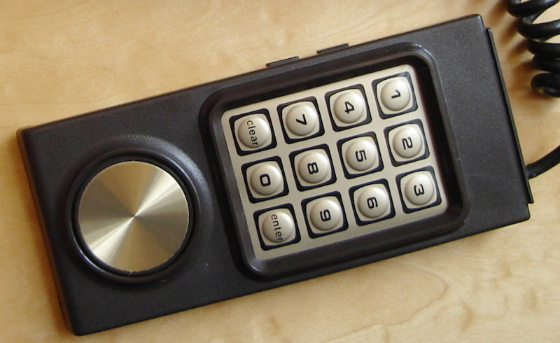
The controller has 12 buttons organized in a way similar to
a telephone keypad, 4 buttons on the sides (The top buttons
on each side perform the same function), and a rotating disc. The rotating
disc and the 12 'telephone' buttons cannot be used at the same time.
The controller I used (Intellivision 1) had 9 wires and a connector
meant to be connected directly to the console's main board. Here's the wire number/color relation table:
Intellivision 1
| # | Color |
|---|---|
| 1 | Brown |
| 2 | Red |
| 3 | Orange |
| 4 | Yellow |
| 5 | Green |
| 6 | Blue |
| 7 | Purple |
| 8 | Dark grey |
| 9 | Light Grey |
Considering that only 9 wires are used without electronic
components inside the controller, it is obvious that the buttons are
organized as a matrix. This means that they must be scanned in software.
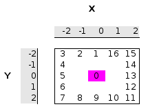
Here's a table I built showing which wires are used:
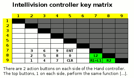
The disc is capable of 16 different directions. The current direction is
output using 6 wires (#2 to #6, #1 as common). As you can see, these are
in conflict with the 'telephone' buttons. This is why the 'telephone' buttons
and rotating disc are not usable together. Notice also that there is always
only 1 bit of difference between adjacent directions. Does it remind you of
Grey code?
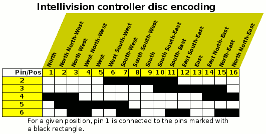
The middle direction is encoded simply by leaving wires #2 to #6 not connected
with #1.
